The basic design problem remains unchanged from RoboBoat: construct a system capable of autonomously navigating through several predefined obstacle courses which reflect real world maritime scenarios.
Navigation Tasks
Primary Objectives
The tasks we plan to accomplish are directly inspired by RoboBoat’s 2024 competition.
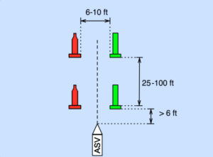
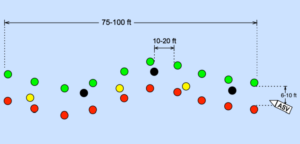
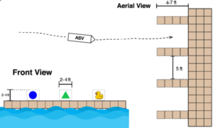
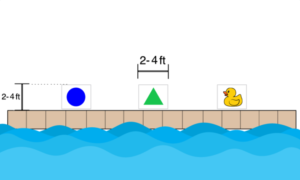
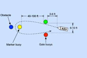
The images above show the main three tasks we plan to accomplish. In the first, our ASV must navigate through two sets of gates, each of which consists of a large red and green buoy (61” height, 9” diameter). In the second task, the ASV must navigate through a more complex set of gates and avoid both black and yellow buoys, while simultaneously counting the number of “ducks” or yellow buoys. All buoys in Task 2 are significantly smaller (11.5” height, 8” diameter). Finally, the third task requires the ASV to approach a docking bay with several images, only one of which is a yellow duck. The vehicle should identify the duck and dock at the corresponding bay and remain for 30 seconds, without running into the dock.
Primary System Requirements
The primary tasks we wish to accomplish enforce several key design considerations. First, our sensor suite must allow the ASV to identify and locate certain objects (green, red, black, and yellow buoys, colored shapes, yellow duck). This means the vehicle must be able to sense both distance and color in order to accurately perceive its environment. Assuming that the initial alignment of the ASV relative to the first set of buoys is unknown, the vehicle must be able to sense objects at least between 6 and 20 ft (based on the distance between sets of buoys in Task 2).
Next, our software system must be able to interpret this sensor input and output control signals to the propulsion system accordingly.
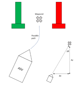
The figure above demonstrates one strategy for implementing a path planning algorithm. Once the vehicle identifies the set of green and red buoys, it sets a waypoint as the midpoint between each buoy. Based on this waypoint, the vehicle can determine a path which will lead it through the gate – for example, the vehicle knows it must adjust x meters horizontally in the time that it travels y meters (distance to buoys), meaning it must adjust its current heading by theta degrees.
We must then translate this waypoint into tangible motor outputs.
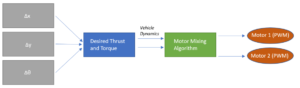
As shown in the figure above, we can use our generated path to compute a desired thrust and torque for the vehicle. Based on the vehicle dynamics, we can then determine the commands which should be sent to our propulsion system.
Since these algorithms depend on vehicle localization – having a sense of where the vehicle is and where it’s pointed – our sensor suite must also include some combination of position and orientation sensors. The roll and pitch angles are not important for an ASV (compared to a drone, for instance); however, we should at the very least be able to keep track of the vehicle’s heading (yaw). In addition, we are unable to use GPS indoors, but determining the vehicle’s relative position (by detecting objects) is sufficient.
In addition, the figure above demonstrates the importance of knowing the vehicle dynamics – mainly thrust, torque, speed, and turning radius capabilities. Without an accurate understanding of these characteristics, it is unlikely that our vehicle will be able to navigate without veering off course or crashing into obstacles. We must conduct significant empirical testing with our vehicle in the pool and document these quantities to be able to successfully implement our central control algorithms.
Task 3 requires a more sophisticated object detection strategy, as classifying colored shapes and images is more nuanced than detecting and avoiding buoys. Training an object detection model via a machine learning algorithm is one option to identify the yellow duck. We may also be able to accomplish this task using a simpler algorithm which considers the relative roughness of the duck compared to smoother shapes. This would allow us to avoid the extensive process of curating a custom data set and training a neural network. We could also look into asking a prior participant in RoboBoat to share a premade training set.
For our primary objectives, speed of the vehicle (and therefore maximum thrust capability) is not a major concern. Rather, the main requirement of our propulsion system is maneuverability. Thrust considerations should be taken account to ensure that the vehicle can successfully navigate between each set of buoys as in Tasks 1 and 2. Assuming the worst-case scenario of a 6 ft wide gate with an obstacle directly in the middle, the smallest gap which the ASV must navigate through is 3ft. Given our current hull which is about 2ft long, this is about 1.5 hull lengths.
Scoring Criteria
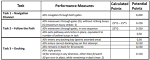
The table above summarizes the scoring criteria for Tasks 1-3. Task 1 is graded on a complete or incomplete basis. For Task 2, points are awarded for each gate the ASV successfully navigates through and deducted for each obstacle the vehicle hits. Additional points are awarded for demonstrating that the ASV successfully counted the number of yellow buoys. Finally, for Task 3, points are awarded separately for entering any docking bay, entering the correct docking bay on the first attempt, and style points.
Additional Tasks
The RoboBoat competition features a total of 8 tasks; however, teams can choose to attempt as many or as few as they wish.
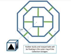

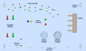
These images show the remaining competition tasks. In Task 4, the ASV approaches the same docking bay used in Task 3 and identifies the target (yellow duck) before squirting water on it. Ideally, the vehicle should deliver a steady stream of water on the target for 5 seconds continuously. In Task 5, the ASV navigates through two sets of gates and then back to its starting point in as little time as possible. For Tasks 6 and 7, the ASV must collect objects (rubber ducks and racquet balls) from the collection octagon and deliver them to the corresponding areas (duck nest and beaver nest, respectively) in the delivery octagon. Finally, Task 8 (“Return to Home”), requires the vehicle to navigate back to its starting position (wherever it initially began the course). The full competition course is shown below.
Additional System Requirements
Attempting Task 4 would involve implementing an additional mechanical system (water gun) and integrating its controls into our existing system. Task 5 builds on our primary objectives, but would require us to tune our control system to maximize movement speed. In addition, it introduces a new color of buoy (blue). Tasks 6 and 7 require manipulation of objects that are floating in the water. Finally, Task 8 would require our navigation system to keep track of its starting position. In general, this is easiest to accomplish using GPS, which we are unable to do. However, it may be possible to maintain a sense of absolute location using landmarks in the Natatorium.
Overall, Tasks 1-3 encompass the core requirements of autonomous navigation, which is the focus of our project. The remaining tasks introduce additional requirements which add a degree of complexity that is not within the scope of our design, (for example, incorporating the water gun for Task 5 or a robotic arm to manipulate objects in Tasks 6 and 7). Given the current state of our design (discussed in detail in section 4.3) and timeframe (discussed in section 5), it is unlikely that we will attempt any of Tasks 4-8.
ASV Subsystems
ASV design presents a complex challenge due to the number of interdependent components required to achieve a functional design. We chose to divide our design into three main subsystems: 1. Hull; 2. Propulsion 3. Electronics and Controls.
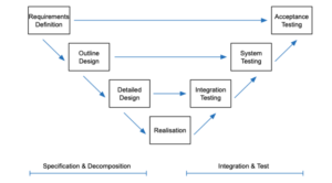
Consistent with the V-model of systems engineering shown above, we first define the requirements of each individual subsystem (left portion of the “V”), and then consider how to integrate each into a cohesive final system (right portion of the “V”).
Hull
A hull must be positively buoyant and allows the vehicle to float on the surface. Key design considerations include material choice, hull shape, weight and size. According to RoboBoat’s rules, the vehicle should be less than 140 lbs (ideally less than 70 lbs) and no larger than 3ft x 3ft x 6ft.
Propulsion
We must design a propulsion system which allows the vehicle to move through the water. The system must generate enough force and torque to allow for basic maneuverability (forward, reverse, and turning) so that the vehicle can navigate through the course. Per RoboBoat’s rules, the system must be battery powered with no battery having a voltage exceeding 60V DC. No combustion engines can be used. In addition, the vehicle must have two kill switches, a hard-wired on-board stop system, and a wireless remote emergency stop on its own frequency link.

This table summarizes the requirements and scoring guidelines for the hull and propulsion system. There is no direct scoring benefit for a smaller hull, as long as it meets the basic size constraints. In general, maximizing points in this area involves minimizing weight and maximizing thrust capabilities.
Electronics and Controls
Inherent with being an autonomous craft, the vehicle should be fully autonomous with all computation occurring on-board. We must develop a sensor suite which allows the vehicle to perceive its environment to support key tasks such object detection and vehicle localization. In addition, we must include the electronics (processing units) and central control algorithms to support autonomous navigation. The software system must be able to process sensor data and map these inputs to tangible motor outputs, making decisions autonomously based on the vehicle’s current objective. Finally, a battery system must be developed to power all electrical components.
Integration
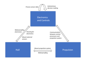
Integrating each subsystem is crucial to ensuring the success of our project. In selecting our hull, we must ensure ample space to house internal electronics as well as the ability to mount external sensors while maintaining the ability to move with a propulsion system. Similarly, the processors and micro controllers we include must be able to communicate with both the sensor suite and propulsion system. Finally, the ability to waterproof all sensitive electrical components must be taken into account. These interdependencies are summarized in the figure below.
With RoboBoat being so interconnected, communication amongst team members is crucial for success. This will be especially relevant when we begin testing the autonomous decision making which utilizes the sensors for data. If sensors get added, removed, or moved without proper documentation this could cause problems. Similarly, if the boat gains weight and large components are added, that may impact our thrust calculations and again impact our decision-making system. To combat this, the team has made a group-chat to document our changes as we make them. All members also keep individual logbooks where they update what they have done during working periods.
Course Construction
A key challenge we will face will be replicating the RoboBoat challenge course in the W&L Natatorium. The RoboBoat website includes details about the course and individual tasks (as discussed abovce); however, we will likely have to take liberties given the differences in the environment. For example, the natatorium is much smaller than the pond used for the actual competition, meaning the location and spacing of each task will have to be modified. Furthermore, the pool is inside rather than outside which may impact GPS and location systems. This means our system will rely heavily on relative positioning within the pool. In addition, the pool will likely not exhibit surface currents, compared to a body of water outside on a windy day. This makes dealing with unwanted drifting and movement easier for us. Finally, cost limitations prevent us from using the exact buoys and obstacles seen in the competition, which has led to us coming up with creative alternatives.