Hull and Propulsion
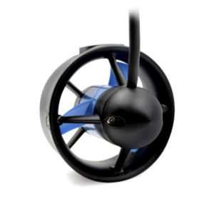
Our initial research into the hull and propulsion system was centered around a careful review of past RoboBoat entries, each of which submitted a publicly available technical design report (see “Meet the Teams”). There were several common themes in these reports. Namely, the vast majority of boat hulls were manufactured by the team (mostly out of fiberglass), as shown in Figure 1. In addition, high-end underwater thrusters (such as the BlueRobotics T200, shown in Figure 2) were purchased and mounted to the hull to provide propulsion which we found would not be feasible due to budget constraints. This led us to consider cheaper alternatives.

Trash Boat
First, a combination of in-house materials such as plywood, plastic, and empty water jugs were considered for the creation of a homemade “trash boat”.
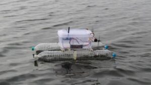
This solution, shown in Figure 3, offers a cheap and relatively easy manufacturing task but presents concerns with maneuverability and durability. Especially with a fully developed boat equipped with batteries, sensors, and CPU, it is hard to know if the fans would be able to propel the boat forward or if it would even be buoyant with all the added weight. Still, because of the ease of assembly, this option is still being considered as potential backup plan or temporary testing vessel.
Kids kayak with pumps
Another option was to purchase a kid’s kayak. We purchased this kayak, (6 ft x 2 ft x 9 in). This purchase provided us with a completed hull and ample space to mount electronics; however, questions remained on how to integrate a propulsion system. An initial suggestion from Professor Kuehner was to consider using a pump as a water jet to propel the boat.
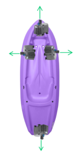
Figure 4 shows an idea for a combination of pumps which would allow the boat to maneuver in the water. With a system like this, the boat would behave like a satellite, with a combination of jets which are either “on” or “off”. This was an attractive option due to its low price (for example, this 12V DC water pump for $13.69) but had several drawbacks. First, there was not an easy way to integrate the pumps with our control system, as they were designed to be turned “on” or “off” manually and flow continuously at a fixed rate. This would make precise small turns, such as those in Task 2, much more difficult. In addition, mounting pumps to the hull was highly nontrivial, as the kayak is not easily machined.
Furthermore, the volumetric output of DC pumps is relatively low so we considered using AC pumps instead as these could produce more thrust.
AC pumps feature a higher volumetric flow rate and consequently can produce greater thrust. For example, this 2200 GPH AC pump can produce about 19N of force. However, since our entire system must be battery powered, this would require an AC inverter on board the vessel, which entails serious safety concerns. In the event that the boat capsized, AC current in a pool with high chlorine content could cause significant injury or death to someone in the pool.
Kids Kayak with sidewheels
Large side wheels in the style of an old riverboat were also considered for propulsion, as pictured in Figure 5. The benefit of these would have been ease of installation when compared to a submersible thruster or through hull motor design, along with the possibility of allowing for pure rotation of the vehicle about its central axis (highly maneuverable). Furthermore, this was a relatively novel idea that we had not seen in any past RoboBoat participants; ultimately, size constraints stopped us from pursuing this option. In the context of task 2, the vehicle may have to navigate between gaps as small as 3ft. With the kayak’s width already being 2ft, adding wheels (additional width) to the side of the vehicle would make clearing these small gaps extremely difficult.

Kids kayak with thrusters
The remaining viable option was thus a propeller powered by a motor. At this stage, we began to heavily consider the BlueRobotics T200 thrusters due to their popularity in the competition. The benefit of these thrusters is their high quality and high thrust output, as well as ease of integration with the control system. By purchasing the BlueRobotics electronic speed controller and writing just a few lines of code, we could quickly test our thrusters. The main concern at this point was how to mount these thrusters to the kayak. The two clear options were mounting the thrusters to the bottom of the kayak and drilling through the bottom of the hull, and mounting the thrusters off the side via some sort of harness. Ultimately, concerns about damaging the hull and the overall machineability of the kayak left us thinking of alternatives.
RC Bait Boat
Finally, we explored the possibility of purchasing a radio-controlled (RC) boat and customizing it to fit our needs. We chose to purchase this RC bait boat made by Creasea Products, shown in Figure 6.
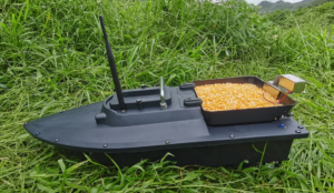
The boat is small (28 in x 11 in), can support a load of 4.5 kg, and is capable of speeds up to 5 mph. In addition, it comes with two 12V DC Motors, each of which draws about 2.5A of current at full power, propellors, and a 12V, 10Ah Lithium polymer battery. The RC boat offers the major advantage that the thrusters were already integrated into the hull and the entire system was waterproofed. In addition, there is ample space inside the boat to house electronics, as well as space on top of the boat to mount sensors.
Electronics and Controls
The electrical and software systems necessary for autonomous navigation require a multitude of different components. In order to successfully integrate them, we had to make careful choices in each segment. We have broken the electronics portion of RoboBoat into several categories.
Processing Units
The first electrical component we looked at was the computer processing unit (CPU) for the boat. This serves as the brain behind the on-board decision making which is required by the competition. It must be programmed to process input streams of data from our environmental sensors, determine a course of action based on the current objective, and relay tangible commands to the motor control system.
After the literature review of competition reports, it was clear that many teams spend large sums of money on high-end processors (such as the NVIDIA Jetson AGX Xavier, for $3000). We searched for cheaper alternatives and had three leading options, the Raspberry Pi 4, the Jetson Nano Developer Kit, and the ODROID M1-S, all seen in Figure 7 below.
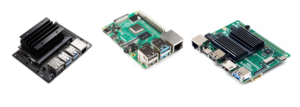
These three were selected as finalists because of their low-price points – $149, $55, and $49 respectively – and recommendations from faculty. Ultimately, the Raspberry Pi 4 was selected out of the three. This was mainly due to the popularity of the Raspberry Pi which boasts a large support community and robust publicly shared libraries. Raspberry Pi can be easily programmed in python to communicate with a variety of sensors. We were also familiar with the Raspberry Pi interface and set-up prior to the project, and had access to several of them without the need of purchasing them. Finally, the Pi is the smallest (3.3in x 2.2in) and lightest (2.08 oz) of the three, which is important since we are working within a constrained hull.
Microcontrollers
To interface with the motor control unit, we chose a Teensy 4.0. Much like the Raspberry Pi, this was chosen because of ease in programming and interfacing with other electrical components. It is compatible with the Arduino IDE and provides all the functionality we need to implement motor control (PWM pins and serial communication). In addition, the Teensy 4.0 (1.15in x 0.7in) is significantly smaller than other microcontrollers, such as the Arduino Uno (2.7in x 2.1in).
Distance Sensors
Detecting objects is a crucial part of autonomous navigation. For Tasks 1 and 2, we need to be able to detect green and red large buoys as well as smaller black “obstacles” and yellow “ducks”.
We initially considered several distance sensors to aid in detecting objects. Our idea was to use an array of these sensors across the boat and to scan the vehicles surroundings. By “sweeping” across a buoy, there should be noticeable drop in measured distance as the object enters and then leaves the sensors field of view.
Ultrasonic Sensor
We first tested a Sparkfun HC-SR04 ultrasonic distance sensor, which works by sending out a sound wave and measuring the time it takes to bounce back. This sensor was chosen because we had it on hand in the lab and the data sheet stated up to 4 meters of range. To assess the viability of this option, we compared the actual distance of a balloon to measured distance. We tested distances over a range from 0 to 180 cm (or such point that the sensor could no longer detect the balloon), taking 10 measurements at each increment of 20 cm. Figure 8 below demonstrates the results of this experiment.

Due to the curved surface of the balloon (which reflects the surface of the buoys and obstacles in the competition) as well as the 15-degree field of view for the sensor, it was difficult to interpret exactly what was being “seen” by the sensor during this experiment, which may explain the high inaccuracy at 40 cm. The main takeaway from this experiment is that measured distance became very inaccurate after at about 1.6 m. Any further than this, and the sensor could not detect any object at all, as evidenced by an uninterpretable output of 1200 cm.
Laser time-of-flight sensor
We also tested an Adafruit VL53L1X laser time-of-flight sensor. This sensor was chosen because it used light instead of sound waves and it also stated a 4 m range. It also is customizable in FOV, depth mode, and can easily chain with other sensors via a multiplexer using I2C protocol. Another unique aspect that drove this choice was the claim that measurements can be made through cover window materials which would allow us to protect it from splashing water. We performed the same experiment described for the ultrasonic sensor, taking 10 measurements at each 20 cm increment until such point that the sensor could no longer detect the balloon.
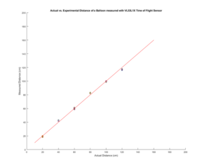
Figure 9 shows the results of testing the time-of-flight sensor. Similar to the ultrasonic sensor, we observe accurate measurements up to a certain point. At about 1.2 m, this sensor is no longer able to detect the balloon, as evidenced by an output of “None”. It is important to note that we were operating the sensor with its default settings (short mode in ambient light). Customizing these settings could lead to a larger distance range. For example, the sensor claims a range of 4m in “dark mode”, which is obviously problematic since the vehicle will be operating in a bright pool.
Overall, these distance sensors by themselves do not provide the functionality needed to accomplish our primary navigation tasks. Based on the starting position of the vehicle in both Tasks 1 and 2, we must be able to detect objects at least 6 meters away. Furthermore, these sensors lack the ability to perceive color. We are still considering implementing an array of distance sensors, most likely the VL53L1X, as a redundant “emergency stop” system. The VL53L1X is the favorite as it can easily be chained with its Qwiic connector pinouts and an I2C protocol multiplexer.
Stereo Vision
Cameras are the clear winner when it comes to accurately identifying objects and detecting both distance and color – the primary capabilities needed to accomplish the RoboBoat tasks. Initially, high-end dual-lens cameras such as the StereoLabs Zed Mini and Intel Realsense were considered due to their powerful machine learning capabilities. These cameras are expensive ($400 entry point with a total budget of $1000) and difficult to program. In addition, we determined that the level of sophistication provided by these options were overkill for what we need to accomplish. For example, the Zed cameras boast 3D body tracking – they can accurately identify humans within their field of view and differentiate between different body parts (head, neck, nose, shoulder, elbow, wrist, to name a few). For each identified object, the camera can output position and velocity information as well as dimensions (length, width, and height). Clearly, this is beyond the scope of what is necessary to accomplish our navigation tasks.

As an alternative to these high-end cameras, we considered a simpler system which employs standard USB cameras and relies on OpenCV, Python’s open-source computer vision library. OpenCV offers built-in computer vision algorithms capable of detecting objects and which can be tuned to fit our needs (detect the specific buoys and other obstacles which are part of the course). To allow for depth perception, two of these USB cameras can be connected to create a stereo vision system. To save money, we elected to create our own stereo vision system using two ELP Megapixel USB cameras, each of which features a frame rate of 60 fps at a resolution of 1280×720. This specific model was chosen as it was available to borrow immediately and highly regarded by an advising professor. The combination of these cameras will serve as the centerpiece of our perception system.
Absolute Orientation Sensor
Having a sense of the boat’s current orientation is another key part of implementing an autonomous navigation system. At the very least, the vehicle needs to know its current heading. For example, in the scenario that the boat identifies a set of buoys directly in front of it, an algorithm can be employed to go forward while maintaining the current heading. Without this functionality, the boat could easily veer off course.
An absolute orientation sensor can be used to accomplish this. We initially selected the Bosch BNO-055, a 9-DOF accelerometer, gyrometer, and magnetometer combination which features on-board sensor fusion and is capable of outputting exact Euler angles (roll, pitch, yaw/heading) to within 1 degree of precision. This sensor can easily communicate with a Raspberry Pi via I2C protocol. To assess this option, we performed an experiment to compare measured heading to actual heading. We rotated the sensor through a range of 180 degrees (using a protractor), taking 5 replicate measurements in increments of 10 degrees. The results of this experiment are summarized in Figure 11 below.

We observe that the BNO-055 is both highly precise and accurate. With the sensor stationary, measured heading does not vary more than a few tenths of a degree, as evidenced by the tight clusters of data points above. In addition, measured heading values were very close to actual heading, differing by at most 1 degree.